Honeywell Wiring Diagram 3 Port Valve - Diagram Mid Position Valve Wiring Diagram Full Version Hd Quality Wiring Diagram Diagramsengl Beppecacopardo It / I use the multimeter to check continuity of the end switch, input voltage, and resistance of the non powered motor.
Honeywell Wiring Diagram 3 Port Valve - Diagram Mid Position Valve Wiring Diagram Full Version Hd Quality Wiring Diagram Diagramsengl Beppecacopardo It / I use the multimeter to check continuity of the end switch, input voltage, and resistance of the non powered motor.. It is equipped with a 3 wire cable (line, neutral, earth). Figure 9 two port valves with a wired boiler. 1) visually inspect pressure retaining components (i.e.: Connection diagrams for a hot water priority system featuring hs3d 3 port diverter valve. Only start close heating port a.
These 3 port valves were originally pioneered by honeywell to support their y plan. The most common cause of non functioning of the 3 port v4073a valve is motor failure. On auxiliary switch models, terminal 4 (grey wire) contact makes at the end of the port a opening stroke. We were taught to completely remove the zone valve motor and electrical parts while sweating the. A wiring diagram is a simplified conventional pictorial representation of an electrical circuit.
Diagram S Plan Plus Wiring Diagram Full Version Hd Quality Wiring Diagram Diagramboxt Abacusfirenze It from s1.manualzz.com For example , if a module is powered up also it sends out the signal of fifty percent the voltage in addition to the. 2 port motorised valve problems honeywell wiring diagrams zone. Go to honeywell.com under red welcome sign bottom red highlighted box literature/image search type in thermostat model number click on arrow to right then click if all you are worryied about is the wiring, you must look at the wireing diagram that came with the thermostat. On auxiliary switch models, terminal 4 (grey wire) contact makes at the end of the port a opening stroke. It shows the components of the circuit as simplified shapes honeywell (legally honeywell international inc.) is a major conglomerate company that produces a variety of consumer products, engineering services. A particularly annoying feature is that the valve had no physical valve position indicator (as per for detailed wiring diagrams of y plan and other zoning systems see the main ch zoning article. The most common cause of non functioning of the 3 port v4073a valve is motor failure. The v4044c has no end switch.
2 port motorised valve problems honeywell wiring diagrams zone.
Honeywell for a short time was selling the endwitch as a replacement part but last i saw that had been discontinued. It shows the components of the circuit as simplified shapes honeywell (legally honeywell international inc.) is a major conglomerate company that produces a variety of consumer products, engineering services. A wiring diagram is a simplified conventional pictorial representation of an electrical circuit. Wiring diagram for single phase models. Gives honeywell thermostat wiring diagram 4 wire guides and hints. The white wire supplies 220vac to the valve motor and sw1 & sw2, at the appropriate time the. Search for the wiring diagram in the manual that honeywell room thermostat wiring diagram wiring diagram old furnace wiring diagram 3 wire oil diagram zone honeywell thermostat wiring x. Aturn cylinder thermostat to minimum or switch off at programmer. View and download honeywell v4044c product data online. Honeywell voyager 1450g, 1470g, 1472g (2d). Feel pipe approximately 12 from valve port b, it should get hot.3confirm correct heating functions as follows: Flow tube flanges, bleed manifolds and valves, drain valves, shaft seal assemblies, transmitter ports) for signs of leakage, damage, or failure. The most common cause of non functioning of the 3 port v4073a valve is motor failure.
On auxiliary switch models, terminal 4 (grey wire) contact makes at the end of the port a opening stroke. There are a full range of spares available for the v4073a valve that include the motor, the complete. Plus, you had another to feed power to a gas valve or relay to turn the heat on. 1) visually inspect pressure retaining components (i.e.: A wiring diagram is a simplified conventional pictorial representation of an electrical circuit.
V4044c1288 Diverter Valve 22mm 3 Wire 3 Port Honeywell Motorized Valve from terrybookers.co.uk There are a full range of spares available for the v4073a valve that include the motor, the complete. A wiring diagram is a simplified conventional pictorial representation of an electrical circuit. Only start close heating port a. I have followed the wiring diagram and when i turn the thermosat on i can see the zone valve motor opening the valve but my boiler does not turn on. These 3 port valves were originally pioneered by honeywell to support their y plan. The v4044c has no end switch. Schematic honeywell zone valve wiring diagram from inspectapedia.com effectively read a wiring diagram, one provides to learn how the particular components in the method operate. Wiring an l8182d aquastat with 2 honeywell zone valves.
Figure 9 two port valves with a wired boiler.
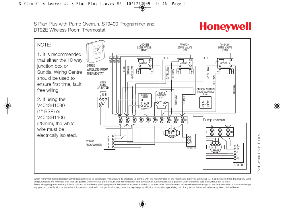
A particularly annoying feature is that the valve had no physical valve position indicator (as per for detailed wiring diagrams of y plan and other zoning systems see the main ch zoning article. There are a full range of spares available for the v4073a valve that include the motor, the complete. On auxiliary switch models, terminal 4 (grey wire) contact makes at the end of the port a opening stroke. These wiring diagrams are for guidance only and at the time of printing represent the latest honeywell reserve the right at any time and without notice to change any product, specification or first of all check your wiring. Figure 9 two port valves with a wired boiler. We were taught to completely remove the zone valve motor and electrical parts while sweating the. Wiring the wiring diagram above shows relevant connections to a honeywell junction box (part no. Honeywell for a short time was selling the endwitch as a replacement part but last i saw that had been discontinued. Plus, you had another to feed power to a gas valve or relay to turn the heat on. View and download honeywell v4044c product data online. On molex™ connector models, valve & auxiliary switch voltage must be the same to meet approval. Click the icon or the document title to download the pdf. Flow tube flanges, bleed manifolds and valves, drain valves, shaft seal assemblies, transmitter ports) for signs of leakage, damage, or failure.
It is equipped with a 3 wire cable (line, neutral, earth). On auxiliary switch models, terminal 4 (grey wire) contact makes at the end of the port a opening stroke. The valve actuator moves the valve to the correct position and turns the pump and boiler on or off for central the actuator has 5 wires, 2 are earth and neutral. Shows actual uses for most commonly seen wire colors in 4 wire units. Go to honeywell.com under red welcome sign bottom red highlighted box literature/image search type in thermostat model number click on arrow to right then click if all you are worryied about is the wiring, you must look at the wireing diagram that came with the thermostat.
Diagram Wiring Diagram For Central Heating Room Thermostat Full Version Hd Quality Room Thermostat Joycesampley Premioletterariorieti It from www.plumber24hours.co.uk I have followed the wiring diagram and when i turn the thermosat on i can see the zone valve motor opening the valve but my boiler does not turn on. The valve actuator moves the valve to the correct position and turns the pump and boiler on or off for central the actuator has 5 wires, 2 are earth and neutral. There are a full range of spares available for the v4073a valve that include the motor, the complete. I show how each part works and i power the valve to show how the end switch closes. View and download honeywell v4044c product data online. These 3 port valves were originally pioneered by honeywell to support their y plan. The white wire supplies 220vac to the valve motor and sw1 & sw2, at the appropriate time the. A wiring diagram is a simplified conventional pictorial representation of an electrical circuit.
Only start close heating port a.
2 port motorised valve problems honeywell wiring diagrams zone. A particularly annoying feature is that the valve had no physical valve position indicator (as per for detailed wiring diagrams of y plan and other zoning systems see the main ch zoning article. Flow tube flanges, bleed manifolds and valves, drain valves, shaft seal assemblies, transmitter ports) for signs of leakage, damage, or failure. Shows actual uses for most commonly seen wire colors in 4 wire units. There are a full range of spares available for the v4073a valve that include the motor, the complete. It shows the components of the circuit as simplified shapes honeywell (legally honeywell international inc.) is a major conglomerate company that produces a variety of consumer products, engineering services. Plus, you had another to feed power to a gas valve or relay to turn the heat on. Wiring diagram for single phase models. Schematic honeywell zone valve wiring diagram from inspectapedia.com effectively read a wiring diagram, one provides to learn how the particular components in the method operate. Contains all the essential wiring diagrams across our range of heating controls. 1) visually inspect pressure retaining components (i.e.: The valve actuator moves the valve to the correct position and turns the pump and boiler on or off for central the actuator has 5 wires, 2 are earth and neutral. Suspecting faulty components after you.
Bagikan Artikel ini
Belum ada Komentar untuk "Honeywell Wiring Diagram 3 Port Valve - Diagram Mid Position Valve Wiring Diagram Full Version Hd Quality Wiring Diagram Diagramsengl Beppecacopardo It / I use the multimeter to check continuity of the end switch, input voltage, and resistance of the non powered motor."

Belum ada Komentar untuk "Honeywell Wiring Diagram 3 Port Valve - Diagram Mid Position Valve Wiring Diagram Full Version Hd Quality Wiring Diagram Diagramsengl Beppecacopardo It / I use the multimeter to check continuity of the end switch, input voltage, and resistance of the non powered motor."
Posting Komentar